Views: 9999 Author: Site Editor Publish Time: 2025-02-14 Origin: Site


The standards introduced this time are of great significance in the field of electrochemical energy storage, covering key aspects such as equipment safety, transportation, design, battery characteristics, grid access, and electromagnetic compatibility.
Standards Information Overview
GB 19517 - 2023 "National Electrical Equipment Safety Technical Specifications
GB/T 43868 - 2024 "Electrochemical Energy Storage Power Station Startup Acceptance Procedure
GB/T 36548 - 2024 "Electrochemical Energy Storage Power Station Connection Grid Test Procedure
GB 21966 - 2008 "Safety Requirements for Lithium Primary Batteries and Batteries in Transportation
GB 51048 - 2014 "Electrochemical Energy Storage Power Station Design Specifications
GB/T 34131 - 2023 "Battery Management System for Power Energy Storage
GB/T 36276 - 2023 "Lithium-ion Batteries for Power Energy Storage
NB/T 42091 - 2016 "Technical Specifications for Lithium-ion Batteries for Electrochemical Energy Storage Power Stations
NB/T 31016 - 2019 "Battery Energy Storage Power Control System - Converter - Technical Specifications
T/CNESA 1000 - 2019 "Evaluation Specifications for Electrochemical Energy Storage Systems
GB 2894 - 2008 "Safety Signs and Guidelines for Their Use
The release and implementation of these standards provide solid technical support and guarantee for the standardized development of the electrochemical energy storage field, and are important guidelines that must be followed by companies and related practitioners in the industry.
Energy Storage 3S
These systems work together to ensure the reliable and efficient operation of electrochemical energy storage systems, contributing to a more sustainable and resilient energy future.
1、PCS:Power Conversion System:Converts DC to AC, manages power quality, and ensures safe operation.
Definition: The Power Conversion System (PCS) is a critical component in electrochemical energy storage systems. It is responsible for converting the direct current (DC) produced by the battery into alternating current (AC) that can be fed into the power grid or used by AC loads. The PCS plays a vital role in ensuring the efficient and stable operation of the energy storage system.
Key Functions:
DC-to-AC Conversion: Converts the DC output from the battery into AC power.
Power Quality Control: Ensures the output power meets grid requirements, including voltage and frequency stability.
Energy Management: Manages the flow of energy between the battery and the grid, optimizing the use of stored energy.
Protection and Safety: Provides protection against overvoltage, overcurrent, and other electrical hazards.
2、BMS:Battery Management System:Monitors and controls the battery to ensure safe and efficient operation.
Definition: The Battery Management System (BMS) is an essential part of any electrochemical energy storage system. It monitors and controls the battery's state of charge, state of health, and temperature to ensure safe and efficient operation.
Key Functions:
State Monitoring: Monitors the battery's voltage, current, and temperature in real-time.
Charge and Discharge Control: Manages the charging and discharging processes to prevent overcharging and overdischarging.
Cell Balancing: Ensures that all cells in the battery pack are evenly charged and discharged, extending the battery's lifespan.
Safety Protection: Provides protection against short circuits, overvoltage, and thermal runaway.
3、EMS:Energy Management System:Coordinates the operation of all components to optimize system performance and efficiency.
Definition: The Energy Management System (EMS) is the brain of the electrochemical energy storage system. It coordinates the operation of all components, including the PCS and BMS, to optimize the overall performance and efficiency of the system.
Key Functions:
System Monitoring: Monitors the entire energy storage system, including the battery, PCS, and grid connection.
Control and Optimization: Controls the operation of the PCS and BMS to optimize energy flow and system efficiency.
Data Analysis: Analyzes system data to identify trends and optimize performance.
Grid Interaction: Manages the interaction with the power grid, including demand response and grid support services.
Core contents of each standard EMC
1、GB 19517 - 2023 National Electrical Equipment Safety Technical Specifications
This specification applies to all types of electrical equipment with an AC rated voltage of less than 1000V (1140V) and a DC rated voltage of less than 1500V, covering handheld, portable and fixed equipment, including products or components within the application range of converting chemical energy, light energy and wind energy into electrical energy. Even if the AC voltage generated inside the product is higher than 1000V and the DC voltage is higher than 1500V and cannot be touched, it is also within the scope of the specification.
It stipulates comprehensive requirements for electrical safety hazard protection, such as protection against electric shock, machinery, electrical connections and mechanical connections, operation, power control and other hazards; it also clarifies a series of safety project requirements, including environmental adaptability, casing and protection level, protective grounding, insulation resistance, leakage current, heat resistance, flame retardant properties and other aspects to ensure the safe operation of electrical equipment under various circumstances.
2、GB 21966 - 2008 Safety requirements for lithium primary cells and batteries during transportation
This standard specifically regulates the safety of lithium primary cells and batteries during transportation, and also sets requirements for the safety of packaging used to transport such products. As the volume of lithium primary cells and batteries shipped continues to increase, their transportation safety is of vital importance.
The standard stipulates a number of strict inspection methods and requirements, such as high-altitude simulation, thermal shock, vibration, impact, external short circuit, heavy object impact, overcharging, forced discharge, package drop and other tests. These tests ensure that the battery will not have quality loss, leakage, discharge, short circuit, rupture, explosion, fire and other dangerous situations during transportation, thereby ensuring the safety of the transportation process.
3、GB 51048 - 2014 "Design Specification for Electrochemical Energy Storage Power Stations"
Applicable to the design of electrochemical energy storage power stations with a power of 500kW and a capacity of 500kW·h or above for new construction, expansion or reconstruction, but excluding mobile electrochemical energy storage power stations. Its purpose is to promote the application of electrochemical energy storage technology and make the power station design safe and reliable, energy-saving and environmentally friendly, technologically advanced and economically reasonable.
The specification clearly defines the terms of electrochemical energy storage power stations, such as energy storage units, power conversion systems, battery management systems, etc.; and puts forward specific requirements for the design of power stations, including site selection, layout, electrical system design, fire protection and safety, etc., providing comprehensive guidance for the design of electrochemical energy storage power stations.
4、GB/T 34131-2023 "Battery Management System for Power Energy Storage"
It specifies the comprehensive requirements for battery management systems for power energy storage, including technology, test methods, inspection rules, marking, packaging, transportation and storage, etc. It is applicable to the design, manufacture, testing, inspection, operation, maintenance and overhaul of battery management systems for lithium-ion batteries, sodium-ion batteries, lead-acid (carbon) batteries, flow batteries and water electrolysis hydrogen/fuel cells. Other types of battery management systems can also be implemented as a reference.
In terms of technical requirements, it covers data acquisition, communication, alarm and protection, control, energy state estimation, balance, insulation resistance detection, insulation withstand voltage, electrical adaptability, electromagnetic compatibility, etc., to ensure that the battery management system can effectively monitor the battery operating status and ensure the safe and efficient operation of the battery system.
5、GB/T 36276-2023 Lithium-ion Batteries for Power Storage
It specifies the key terms and definitions of lithium-ion batteries for power storage, as well as a series of key technical requirements closely related to quality and safety, such as energy efficiency, rate performance, cycle performance, short circuit and thermal runaway, and clarifies the corresponding test conditions and test methods.
This standard sets strict requirements on the performance and safety of batteries. For example, in terms of safety performance, detailed provisions are made for the thermal insulation temperature rise characteristics of battery cells, the withstand voltage of liquid cooling pipes, and external short-circuit tests. This will help promote the technological upgrading and transformation of lithium-ion batteries for power storage and promote the high-quality development of the battery energy storage industry.
6、GB/T 36548-2024 "Testing procedures for connecting electrochemical energy storage power stations to the power grid"
It mainly regulates the test of electrochemical energy storage power stations connected to the grid, and clarifies the specific requirements and processes of each test. Its purpose is to ensure that after the electrochemical energy storage power station is connected to the grid, it can operate safely, stably and efficiently with the grid, without affecting the normal power supply and power quality of the grid.
The regulations stipulate multiple aspects including power quality testing, power control and regulation performance testing, fault ride-through capability testing, communication and monitoring function testing, etc., providing detailed testing basis and standards for the access of electrochemical energy storage power stations to the power grid.
7、GB/T 43868 - 2024 "Electrochemical Energy Storage Power Station Start-up Acceptance Procedure"
The acceptance content covers equipment installation and commissioning inspection, electrical performance testing, system function verification, safety protection facility inspection and other aspects to ensure that the power station can be started and put into operation safely and reliably.
It standardizes all aspects of the start-up acceptance of electrochemical energy storage power stations, and clarifies the conditions, procedures, contents, and preparation of acceptance reports. Through strict start-up acceptance, it ensures that the performance and indicators of electrochemical energy storage power stations meet the design requirements and relevant standards before they are put into operation.
8、NB/T 42091 - 2016 Technical Specification for Lithium-ion Batteries for Electrochemical Energy Storage Power Stations
The technical requirements for lithium-ion batteries used in electrochemical energy storage power stations are specified in detail, including battery performance, safety, environmental adaptability, etc. It aims to standardize the production and application of lithium-ion batteries used in electrochemical energy storage power stations and improve the quality and reliability of batteries.
In terms of performance, requirements are put forward for battery capacity, energy efficiency, charge and discharge rate and other indicators; in terms of safety, regulations are made for battery thermal stability, overcharge and over-discharge protection, short-circuit protection, etc.
9、NB/T 31016 - 2019 "Battery Energy Storage Power Control System Converter Technical Specification"
The technical requirements, test methods, inspection rules, etc. are specified for the converter in the battery energy storage power control system. As the key connection device between the battery energy storage system and the power grid, the performance and quality of the converter directly affect the operation effect of the energy storage system.
The technical specifications put forward specific requirements for the power conversion efficiency, power quality, control accuracy, reliability and other aspects of the converter to ensure that the converter can efficiently and stably achieve power conversion and control.
10、T/CNESA 1000 - 2019 Specification for Evaluation of Electrochemical Energy Storage Systems
The specification establishes a comprehensive electrochemical energy storage system evaluation system, evaluating the energy storage system from multiple dimensions, including the performance, safety, reliability, economy, etc. Through scientific evaluation, it provides a reference for the design, selection, operation and maintenance of the energy storage system.
The evaluation indicators cover multiple key parameters of the energy storage system, such as energy efficiency, charge and discharge depth, cycle life, failure probability, investment cost, and operating cost, which will help promote the optimization and development of the energy storage system.
11、GB 2894 - 2008 "Safety signs and their use guidelines"
It stipulates the classification, design principles, colors, shapes, symbols, etc. of safety signs, as well as the use requirements and setting methods of safety signs. In the field of electrochemical energy storage, the correct use of safety signs can effectively warn people of potential dangers and prevent accidents.
For example, in energy storage power stations, by setting up safety signs such as fire prevention, electric shock prevention, and no fireworks, staff and outsiders are reminded to pay attention to safety issues and ensure the safety of personnel and equipment.
EMC related content
With the widespread use of modern electronic devices, the electromagnetic environment is becoming increasingly complex, and the problem of electromagnetic interference is becoming more and more prominent. For equipment and systems in the field of electrochemical energy storage, electromagnetic compatibility (EMC) is crucial.
If the equipment does not have good electromagnetic compatibility, it may be interfered by the surrounding electromagnetic environment during operation, resulting in performance degradation, failure or even damage; at the same time, the electromagnetic interference generated by the equipment itself may also have adverse effects on other equipment and systems, affecting the stable operation of the entire power grid.
Therefore, ensuring the electromagnetic compatibility of electrochemical energy storage equipment and systems is one of the key factors to ensure their safe and reliable operation.
All standards highly emphasize the normal operation and anti-interference capabilities of equipment in complex electromagnetic environments.
This means that the equipment must not only be able to stably complete its own functions, but also have the ability to resist a certain degree of electromagnetic interference to ensure that there will be no malfunctions, performance degradation and other problems in various electromagnetic environments.
At the same time, the electromagnetic emissions generated by the equipment itself should also be strictly limited and should not cause harmful interference to other surrounding equipment to maintain the harmony and stability of the entire electromagnetic environment.
Specific test items
Electrostatic Discharge Immunity ESD IEC61000-4-2
GB/T 34131-2023 explicitly requires that the battery management system should be able to withstand the electrostatic discharge immunity test of level 3 specified in GB/T 17626.2.
In actual applications, electrostatic discharge may be generated during the operation and maintenance of the equipment, such as when people touch the equipment, or when the equipment rubs against other objects. If the battery management system cannot withstand the corresponding level of electrostatic discharge, it may cause serious consequences such as damage to electronic components, data loss, and system crashes.
Electrical fast transient burst immunity IEC61000-4-4
GB/T 34131-2023, NB/T 31016-2019 and other standards have put forward corresponding requirements for the immunity test of electrical fast transient pulse groups.
For example, the energy storage converter should be able to withstand the immunity test of electrical fast transient pulse groups with a test level of 3 as specified in GB/T 17626.4.
Electrical fast transient pulse groups are usually caused by switching operations of electrical equipment, lightning strikes, etc., and are characterized by short pulse duration, high amplitude, and high repetition frequency. If the energy storage converter cannot effectively resist this interference, problems such as abnormal control and output voltage fluctuation may occur, affecting the normal operation of the energy storage system.
Surge (impact) immunity IEC61000-4-5
Most standards involve surge (impact) immunity tests, such as: GB/T 34131-2023 requires that the battery management system should be able to withstand the surge (impact) immunity test of test level 3 specified in GB/T 17626.5.
Surges are usually caused by instantaneous overvoltage or overcurrent due to lightning strikes, grid switching, large equipment startup, etc.
If the battery management system does not have sufficient anti-interference ability when it is subjected to surge impact, it may cause internal circuit damage, component breakdown and other faults, seriously affecting the reliability and service life of the system.
Power frequency magnetic field immunity IEC61000-4-8
GB/T 34131-2023, NB/T 31016-2019 and other standards stipulate the power frequency magnetic field immunity test.
For example, the energy storage converter should be able to withstand the power frequency magnetic field immunity test with a test level of 4 specified in GB/T 17626.8.
In the power system, the power frequency magnetic field is everywhere, especially in places such as substations and distribution rooms.
The energy storage converter is in the power frequency magnetic field environment for a long time. If it cannot resist its interference, it may cause problems such as control signal distortion and reduced measurement accuracy, which will affect the performance of the energy storage system.
Radiated radio frequency electromagnetic field immunity IEC61000-4-3
Some standards put forward requirements for RF electromagnetic field radiation immunity tests. For example, GB/T 34131-2023 requires that the battery management system should be able to withstand the RF electromagnetic field radiation immunity test of test level 3 specified in GB/T 17626.3. In today's highly developed modern communication technology, RF electromagnetic fields are widely present in the environment around us. If the battery management system cannot effectively resist the radiation interference of RF electromagnetic fields, it may be affected by mobile phone signals, wireless communication signals, etc., causing the system to work abnormally.
Other immunity tests
Some standards also cover test requirements such as immunity to conducted disturbances induced by RF fields, immunity to voltage sags, short interruptions and voltage changes, and immunity to damped oscillatory waves.
These tests comprehensively examine the anti-interference ability of equipment in complex electromagnetic environments from different angles.
For example, the immunity test for conducted disturbances induced by RF fields mainly examines the equipment's resistance to RF interference conducted through wires; the immunity test for voltage sags, short interruptions and voltage changes focuses on the equipment's operating stability when the grid voltage fluctuates abnormally; the damped oscillatory wave immunity test is used to evaluate the equipment's tolerance to high-frequency oscillation interference generated by switching operations.
Electromagnetic emission limits
General Requirements
The electromagnetic emission of the equipment must strictly comply with the limits specified in the relevant standards to avoid the adverse effects of electromagnetic interference generated by the equipment on the surrounding environment and other equipment. If the electromagnetic emission of the equipment exceeds the limit, it may interfere with the normal operation of nearby communication equipment, electronic instruments, etc., and even affect the safe and stable operation of the power system.
Specific indicators
The T/CNESA 1000 - 2019 standard clearly stipulates the electromagnetic emission limits of energy storage systems in different application scenarios. In residential, commercial and light industrial environments, energy storage systems should comply with the requirements of GB 17799.3. These environments are more sensitive to electromagnetic interference, and strict limit requirements help to ensure the quality of life of residents and the normal operation of commercial equipment; In industrial environments, energy storage systems should comply with the requirements of GB 17799.4. Although the tolerance of industrial environments to electromagnetic interference is relatively high, it is also necessary to ensure that the electromagnetic emission of energy storage systems will not interfere with industrial production equipment and automation control systems.
Standard room relationship
These standards comprehensively and deeply regulate the equipment and systems in the field of electrochemical energy storage from different dimensions and levels.
From the basic safety technical specifications of electrical equipment to the specific requirements of batteries in transportation, energy storage power station design, battery management system, battery characteristics, etc., to the energy storage power station access to the grid, startup acceptance and system evaluation, a complete standard system has been formed.
EMC-related content runs through various standards and is an important guarantee to ensure the safe and reliable operation of these equipment and systems in complex electromagnetic environments
Without EMC considerations, the stability and reliability of the entire electrochemical energy storage system cannot be effectively guaranteed.
Technical connection
Test methods and requirements
The standards complement and cooperate with each other in EMC test methods and requirements, forming a scientific and complete test system. Different standards target different equipment and systems. In various EMC test items such as electrostatic discharge immunity, electrical fast transient pulse group immunity, and surge immunity, although the specific test objects and parameters may vary, they all follow unified test principles and basic requirements. For example, the EMC test requirements for battery management systems in GB/T 34131-2023 echo the EMC test requirements for energy storage inverters and other equipment in other relevant standards, which together ensure that the electromagnetic compatibility of the entire electrochemical energy storage system is comprehensively and accurately evaluated.
Indicator consistency
Although different standards may have certain differences in specific EMC indicators, this is due to the different functions, characteristics and application scenarios of different devices and systems.
However, their overall goals are highly consistent, which is to ensure that electrochemical energy storage devices and systems can operate normally and stably in complex electromagnetic environments, and to minimize the impact of electromagnetic interference on power grids and other equipment. This consistency of goals enables various standards to coordinate and support each other in practical applications, and jointly promote the healthy development of electrochemical energy storage technology.
Application and YINT electronic Recommendations
These standards provide equipment manufacturers with clear and detailed EMC design and manufacturing requirements.
During the equipment design stage
Manufacturers need to fully consider the electromagnetic compatibility of the equipment according to the standard requirements, optimize the circuit layout, shielding design, grounding measures, etc., and adopt appropriate electromagnetic compatibility technology and materials to improve the equipment's anti-interference ability and electromagnetic emission control level.
During the manufacturing process
Strictly follow the standard requirements for production and inspection to ensure that each device complies with EMC-related standards, thereby improving the quality and reliability of the equipment and reducing the risk of product failures and recalls due to electromagnetic compatibility issues.
Engineering application and acceptance
These standards are important bases for the engineering application and acceptance of electrochemical energy storage projects.
During the project construction process, the construction unit needs to install equipment, wire, and ground according to the standard requirements to ensure that the electromagnetic compatibility of the entire system meets the standards.
In the acceptance stage, the acceptance personnel strictly test and evaluate the EMC performance of the project according to the standards, including various immunity tests and electromagnetic emission limit detection.
Only when the EMC performance of the project fully meets the requirements of the relevant standards can it pass the acceptance, thereby ensuring the safe and stable operation of the power grid and avoiding adverse effects on the power grid due to electromagnetic compatibility issues of energy storage projects.
International standards
In the context of globalization, international trade and cooperation in electrochemical energy storage equipment are becoming increasingly frequent, but the existing standard system may need to be improved in terms of integration with international EMC standards.
Compared with the relevant standards of international organizations such as the International Electrotechnical Commission (IEC), there are certain differences in some test methods, index limits, etc., which may affect the competitiveness and recognition of my country's electrochemical energy storage products in the international market.
The standard requirements are too low
The modern electromagnetic environment is becoming increasingly complex, the sources of electromagnetic interference are increasing and the forms of interference are diverse, so the standard requirements are too low.
EMC pain points and solutions
High-speed switching of switching devices: Inverters usually use switching devices such as insulated gate bipolar transistors (IGBTs) and metal-oxide-semiconductor field-effect transistors (MOSFETs). During the high-frequency switching process, the voltage and current of these devices will change rapidly in a very short time, generating high and . This rapid change will produce rich harmonic components, which will interfere with surrounding electronic equipment through conduction and radiation. For example, when the IGBT is turned on and off, the voltage change rate can reach thousands of volts per microsecond. The resulting high-frequency harmonics will propagate through conductors such as power lines and signal lines, forming conducted interference.
Circuit topology: Different inverter circuit topologies, such as half-bridge, full-bridge, push-pull, etc., will affect the generation and propagation characteristics of electromagnetic interference. For example, due to the characteristics of its circuit structure, a full-bridge inverter will generate large common-mode currents during the switching process. These common-mode currents will form common-mode interference through the inverter casing, grounding system, etc., and radiate electromagnetic energy to the surrounding space.
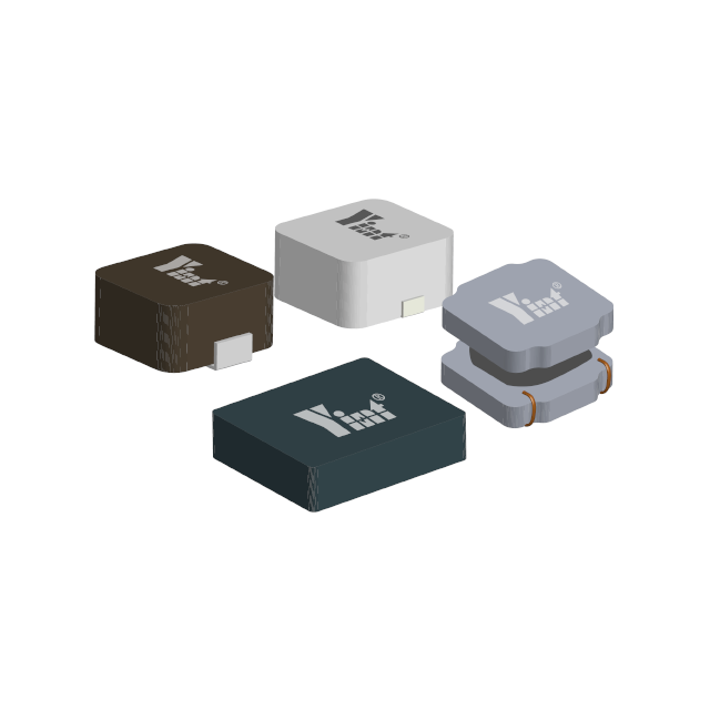
Magnetic components
Transformer: Transformer is a commonly used magnetic component in inverters, used to achieve voltage conversion and electrical isolation. When the transformer is working, the alternating current in its windings will generate an alternating magnetic field, and part of the magnetic field will leak into the surrounding space, forming radiation interference. At the same time, there are distributed capacitances between the windings of the transformer, and high-frequency currents will be coupled to other circuits through these distributed capacitances, generating conducted interference. In addition, the magnetic core of the transformer will generate hysteresis loss and eddy current loss under the action of the alternating magnetic field, and these losses will also generate certain electromagnetic interference.
Inductor: Inductor is used in inverters for filtering, energy storage and other functions. The current change in the inductor will generate an induced electromotive force. When the parameters of the inductor are improperly selected or it works in a high-frequency state, the inductor will generate a large electromagnetic radiation. Moreover, the coupling between the inductor and the surrounding circuits will also lead to the propagation of electromagnetic interference.
Cooling system
Cooling fan: The cooling fan is an important part of the inverter cooling system. Its motor will generate electromagnetic interference during operation.
Heat sink: When the power device is working, the high-frequency current it generates will form a current loop through the heat sink. The heat sink is equivalent to a radiating antenna, radiating electromagnetic energy to the surrounding space.
Wiring and grounding
Irrational wiring: If the wiring inside the inverter is unreasonable, such as the distance between the signal line and the power line is too close, and the lines with different functions are crossed, the electromagnetic coupling between the lines will be enhanced, making it easier for interference signals to propagate between different lines. For example, when the high-frequency signal line is laid in parallel with the power line, the high-frequency interference signal in the power line will be transmitted to the signal line through capacitive coupling and inductive coupling, affecting the normal transmission of the signal.
Grounding problem: Good grounding is an important measure to suppress electromagnetic interference. If the grounding of the inverter is poor, the common mode interference cannot be effectively discharged, and the electromagnetic radiation of the equipment will increase. In addition, if the grounding methods of different circuit parts are inconsistent, a grounding loop may be formed. The current in the grounding loop will generate electromagnetic radiation and introduce external interference signals.
Load characteristics
Nonlinearity of the load: When the inverter drives a nonlinear load, such as a load with a rectifier bridge, a switching power supply, etc., the load will generate harmonic currents. These harmonic currents will be fed back to the output of the inverter, causing the output voltage and current waveforms of the inverter to be distorted, generating additional electromagnetic interference. For example, when the inverter supplies power to a computer or other device, the switching power supply inside the computer will generate a large number of high-order harmonics, which will affect the working performance of the inverter and propagate interference signals through the output and input of the inverter.
Sudden changes in load: Sudden changes in load, such as the input or removal of load, will cause sudden changes in the output current and voltage of the inverter, generating impact current and voltage. This impact will stimulate the circuit inside the inverter to produce high-frequency oscillations, thereby generating electromagnetic interference.
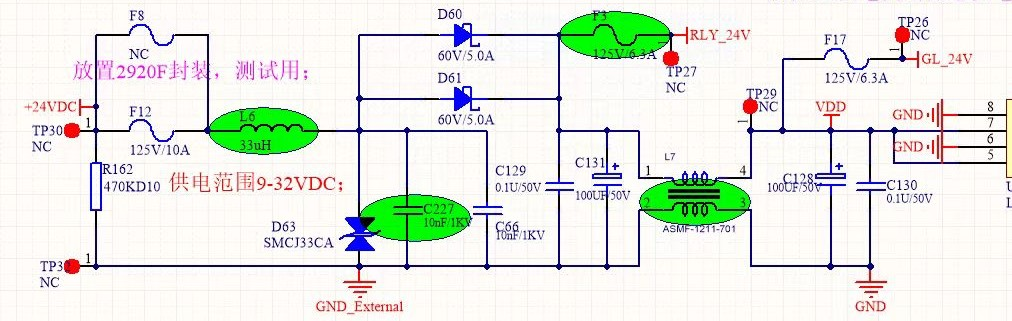
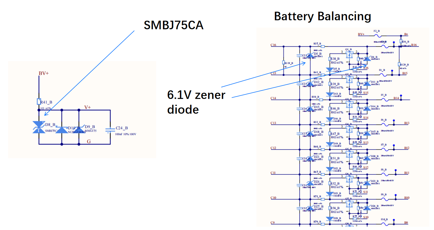
Power Lightning protection design for power input, considering IEC61000-4-5 /GB17626.5 surge test; External factors.
Varistor + GDT is a perfect combination.
Customized TSS semiconductor discharge tubes are also "excellent".
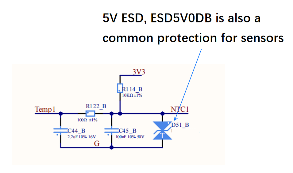
External electromagnetic environment: Example of automobile: BMS is used in vehicles such as electric vehicles. The engine, motor controller, ignition system and other equipment of the vehicle will generate strong electromagnetic interference. When the motor controller controls the operation of the motor, it will generate high-frequency voltage and current changes. These changes will affect the normal operation of the BMS through space radiation and power line conduction. Example of industry: In industrial sites, there are a large number of electrical equipment, such as inverters, electric welders, etc., which will generate electromagnetic interference of various frequencies during operation.
Connecting communication cables: The cables used for communication between BMS and external devices (such as charging piles, host computers, etc.) are easily affected by external electromagnetic interference during signal transmission, resulting in distortion or loss of communication signals. In addition, the communication cables themselves may also radiate electromagnetic interference, affecting other surrounding devices.
Electromagnetic characteristics of battery packs, battery charging and discharging process: During the charging and discharging process, the battery produces changes in current and voltage.
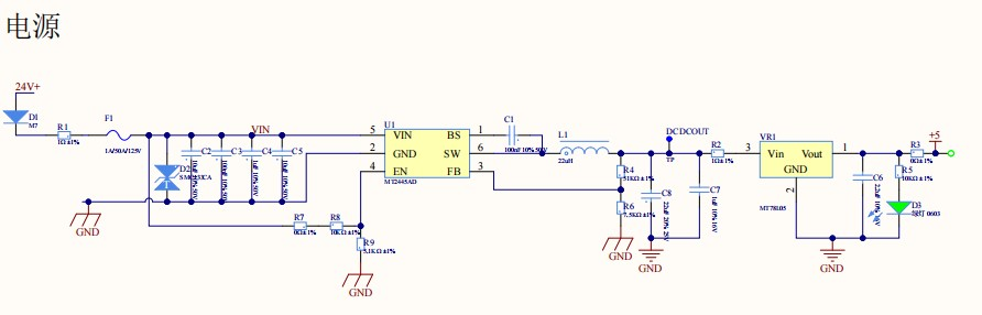
I. Power circuit
DC-DC converter: Different modules inside the BMS provide appropriate power supply voltage. Bulk or boost, the high-frequency switching action of the switching device will generate abundant high-frequency harmonics. These harmonics will not only be transmitted to other circuit parts through the power line, but also interfere with the surrounding electronic components by radiation. Charging and discharging control circuit: During the battery charging and discharging process, these circuits will handle large current changes, and the switching action will also generate electromagnetic interference. For example, when the battery is charged and discharged quickly, the switching devices in the charging control circuit are frequently switched, which will generate strong electromagnetic interference signals.
II. Communication interface
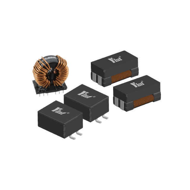
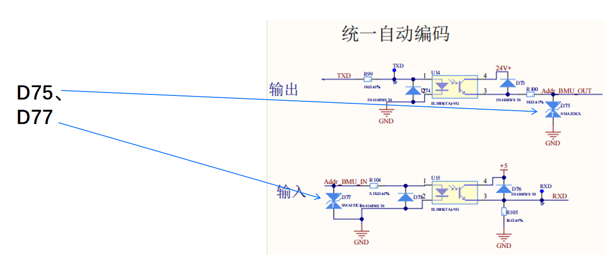
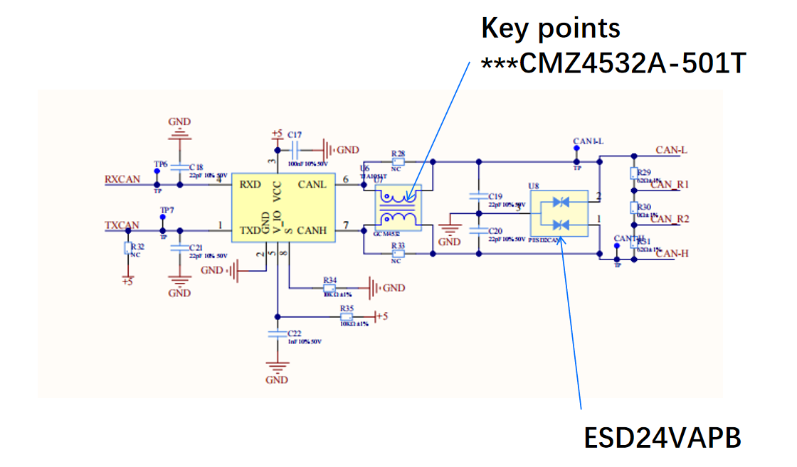
BMS modules usually use CAN, SPI, I2C and other communication interfaces for data transmission. For example, when the CAN bus is transmitting data, the voltage change on the bus will generate high-frequency radiation, and it may also be affected by external electromagnetic interference, resulting in communication errors or data loss. The combination of CMZ4532A-501T common mode inductor and ESD24VAPB can solve the EMC problem of CAN communication. Clock signal: The clock signal of the internal communication system is one of the important sources of electromagnetic interference, which will increase the bit error rate during communication.
III. Unreasonable wiring:
If the distance between the signal line and the power line on the PCB is too close, or the signal lines of different functions cross, the electromagnetic coupling between the lines will increase.
Poor design of the power layer and the ground layer: Problems such as excessive impedance and unreasonable division of the power layer and the ground layer will cause voltage fluctuations on the power and ground planes, generating common-mode interference and differential-mode interference. For example, when there are gaps in the ground layer, the integrity of the ground plane will be destroyed, making the signal return path longer and increasing the possibility of electromagnetic radiation.
EMS Energy Management System Electromagnetic Compatibility EMC (between modules)
Electromagnetic coupling of devices between modules
Interaction interference of PCS: EMS and PCS (power conversion system) need to frequently exchange data and control instructions.
When PCS performs power conversion, the high-frequency switching action of the switching device will generate strong electromagnetic interference. These interferences may be transmitted to EMS through power lines, communication lines, etc., affecting the normal communication and control functions of EMS. Conversely, the control signal sent by EMS may also be interfered by the electromagnetic environment of PCS, resulting in the inability of PCS to accurately execute control instructions, affecting the power regulation and energy distribution of the energy storage system.
Communication interference of BMS
BMS (battery management system) is responsible for monitoring the status information of the battery and transmitting this information to EMS. During the communication process, BMS and battery packs themselves will generate certain electromagnetic interference, and the interference of the external environment may also be superimposed on the communication line. If the anti-interference ability of the communication interface between EMS and BMS is insufficient, it may cause communication data loss and errors, making it impossible for EMS to obtain the battery status in a timely and accurate manner, thereby affecting the safe management and optimization control of the energy storage system.
Stability of the power supply system
Power supply ripple interference:
The normal operation of EMS depends on a stable power supply. The power supply system will generate ripples during operation, especially the switching power supply. The ripple voltage will be superimposed on the DC power supply as an interference signal, affecting the normal operation of the electronic components in the EMS. For example, excessive ripple may cause the working voltage of the chip to be unstable, thereby affecting its calculation accuracy and data processing capabilities, and may even cause serious problems such as system crashes or program runaway.
Power supply transient response problem:
When the internal load of the EMS suddenly changes, the power supply system needs to respond quickly to maintain a stable output voltage. If the transient response capability of the power supply is insufficient, the output voltage may fluctuate greatly at the moment of load mutation. This voltage fluctuation will not only affect the normal operation of each module in the EMS, but may also generate electromagnetic interference, which will be transmitted to other devices through the power line, affecting the electromagnetic compatibility of the entire energy storage system.
We can provide an external 24V power supply
L6; D60, 61; D63; L7 common mode
Let's continue embracing smarter, greener solutions for the future. Stay tuned for more updates on the electronics industry!
Website:https://www.yint-electronic.com/
Email:global@yint.com.cn
Whatsapp&WeChat:+86-18721669954
#ElectronicComponents #AI #5G #Semiconductors #ElectricVehicles #SmartTech #TechInnovation #IndustryGrowth #Sustainability #FutureTech #CircuitProtection #ElectronicsDesign #EngineeringSolutions #Innovation #ESDProtection #PowerElectronics #manufacturing #tvs #esd #pptc #ntc #gdt #mosfet #tss #diode #electronics #factory #semiconductor #components #circuit