Views: 0 Author: Site Editor Publish Time: 2025-02-27 Origin: Site


Principle: According to Maxwell's equations, electromagnetic interference propagates in the form of electromagnetic waves, which contain alternating electric and magnetic field components. Metals have high electrical conductivity and magnetic permeability. When electromagnetic interference is incident on the metal shielding layer, according to the law of electromagnetic induction, the electric field will drive the free electrons in the metal to move in a directional manner, thereby generating an induced current. According to Lenz's law, the magnetic field excited by the induced current is opposite to the incident interference magnetic field, and the two are superimposed on each other to effectively offset part of the interference magnetic field; at the same time, according to the boundary conditions of the electric field, the metal shielding layer can cut off the propagation path of the electric field, thereby achieving a shielding effect.
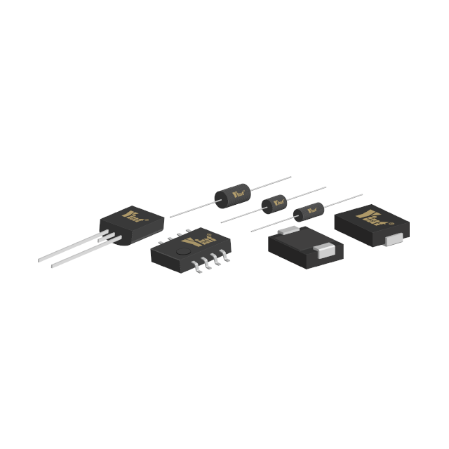
Specific operation: In the motor manufacturing process, based on the electromagnetic properties of the material, aluminum alloys (whose electrical conductivity is about 3.5×10⁷ S/m and relative magnetic permeability is close to 1) and iron-nickel alloys (with high magnetic permeability, such as Permalloy, which can reach 10⁵ in a weak magnetic field) are preferred as motor housing materials. And adopt advanced sealing technology, such as laser welding, metal sealant, etc., to minimize the gaps and holes in the shell to prevent electromagnetic interference leakage. Take the BLDC motor in an industrial automation equipment as an example. It uses an aluminum alloy shell. Through precise CNC processing technology, the gap at the joint of the shell is less than 0.1mm, which effectively reduces the intensity of electromagnetic radiation. For the drive circuit, according to the size of the circuit board and the intensity of electromagnetic interference, a metal shielding cover with appropriate thickness is selected, such as a copper shielding cover with a thickness of 0.5-1mm, and the metal shrapnel is welded by surface mount technology (SMT) to ensure that a low-impedance electrical connection is formed between the shielding cover and the circuit board.
Note: In the shielding design process, the electromagnetic compatibility design guidelines must be strictly followed to avoid the formation of new interference sources between different shielding layers. For example, in automotive electronic systems, the motor housing and the drive circuit shielding cover need to be AC coupled through capacitors, and isolation devices such as optocouplers are used for electrical isolation to prevent new electromagnetic interference caused by the current generated by the potential difference. In addition, the grounding of the shielding layer is very important. According to the grounding theory, it is necessary to ensure that the grounding resistance is less than 0.1Ω to achieve efficient electromagnetic shielding.
2. Careful construction of the grounding system
Principle: According to Ohm's law and Kirchhoff's law, the core purpose of grounding is to provide a low-impedance return path for the current, so that the metal shell of the equipment is at the same potential as the earth. This can not only avoid the high voltage caused by static electricity accumulation and electromagnetic induction from causing harm to equipment and personnel, but also effectively suppress electromagnetic interference based on the principle of electromagnetic induction. When electromagnetic induction occurs in the equipment, the grounding system can quickly introduce the induced current into the earth, thereby reducing the induced electromotive force on the equipment.
Specific operation: The metal shell of the motor is connected to the earth through a dedicated grounding wire. According to the current carrying capacity calculation standard of wires and cables, the cross-sectional area of the grounding wire needs to be accurately calculated and selected according to the rated power of the motor and the maximum short-circuit current that may be generated to ensure sufficient current carrying capacity. In a 5kW industrial BLDC motor, a copper grounding wire with a cross-sectional area of 6mm² is selected after calculation to meet the current carrying requirements under short-circuit current. In the drive circuit, when a multi-layer printed circuit board (PCB) is used, one layer is specifically defined as the ground plane, and professional PCB design software (such as Altium Designer) is used to reasonably layout the ground vias to ensure that the ground pins of each component can be connected to the ground plane nearby. For some key analog circuit parts, such as the position sensor signal processing circuit of the motor, a single-point grounding method is used to effectively reduce the interference caused by the ground potential difference.
Note: Different grounding systems must strictly follow the electromagnetic compatibility design specifications to avoid mutual interference. For example, in medical equipment, strong current grounding and weak current grounding must use independent grounding trunks, and equipotential connections must be made at the grounding bus to prevent strong current interference from entering the weak current circuit through the grounding system. At the same time, according to relevant standards (such as GB 50169-2016 "Electrical Installation Engineering Grounding Device Construction and Acceptance Specifications"), the reliability of the grounding connection is regularly tested to ensure that the grounding resistance is always maintained within the specified range.
3. Reasonable configuration of filters
Principle: The conducted interference on the power line mainly includes common mode interference and differential mode interference. The common-mode inductor uses its special structure of two-wire parallel winding to make the magnetic flux generated by the common-mode current in the two windings superimpose each other, thereby presenting a high impedance characteristic to the common-mode current and effectively suppressing the common-mode interference; the differential-mode capacitor has a low impedance characteristic to the differential-mode current based on the capacitive reactance characteristic of the capacitor (X_C = \frac{1}{2\pi fC}), and can bypass the high-frequency differential-mode interference signal. The low-pass filter on the signal transmission line is based on the frequency response characteristics of the LC circuit. By reasonably selecting the parameters of the inductor and capacitor, it allows low-frequency signals to pass through and effectively attenuates high-frequency interference signals.
Specific operation: At the power input end, according to the voltage, current and interference frequency range of the power supply, use circuit analysis software (such as PSpice) for accurate calculation, and select the common-mode inductor and differential-mode capacitor with appropriate parameters to form a filter. For example, for a 220V, 50Hz AC input power supply, the inductance of the common-mode inductor can be selected as 5mH, and the capacity of the differential-mode capacitor can be selected as 0.47μF. In the BLDC motor drive power supply of a household air conditioner, after using the filter with this parameter, the conducted interference on the power line is greatly reduced, meeting the relevant electromagnetic compatibility standards. On the signal transmission line, according to the frequency and bandwidth of the signal, the filter design theory is used to design a low-pass filter with a suitable cutoff frequency. For example, for a 1MHz signal transmission line, the cutoff frequency of the low-pass filter is set to 5MHz by calculation, which effectively filters out high-frequency interference signals.
Note: The parameter selection of the filter must be accurately matched with the actual impedance and frequency characteristics of the circuit, otherwise the expected filtering effect may not be achieved. At the same time, the installation position of the filter is crucial. It is necessary to follow the principle of the shortest electromagnetic interference propagation path, try to be close to the interference source and the protected circuit, and reduce the coupling of the interference signal during the transmission process.
Principle: According to the electromagnetic torque formula of the motor T = K_tI (where K_t is the torque constant and I is the current), the frequency and duty cycle of the PWM signal will directly affect the current and voltage change rate of the motor, thereby generating electromagnetic interference of varying degrees. When the PWM frequency resonates with the natural frequency or sensitive frequency of other circuits, the interference intensity will increase exponentially according to vibration theory. Random PWM technology introduces a pseudo-random sequence to disrupt the fixed frequency of the PWM signal, so that the interference energy is evenly distributed in a wider frequency range. According to the power spectrum density theory, it effectively reduces the interference intensity at a specific frequency.
Specific operation: When designing the PWM control algorithm, use spectrum analysis tools (such as FFT analyzer) to comprehensively analyze the operating frequencies of other circuits in the system to determine a reasonable PWM frequency range to avoid overlap with sensitive frequencies. For random PWM technology, a pseudo-random number generator based on a linear feedback shift register (LFSR) is used to generate a frequency-varying control signal, so that the frequency of the PWM signal fluctuates randomly within the set frequency range, and the fluctuation range can generally be set to ±15%. In the BLDC motor control system of an electric vehicle, the electromagnetic interference intensity was reduced by more than 10dB after the random PWM technology was used, effectively improving the electromagnetic compatibility of the system.
Note: When using random PWM technology, its impact on the motor's operating performance must be fully considered. Due to the random change of frequency, the torque pulsation of the motor may increase. According to the principle of motor dynamics, the motor's operating status needs to be monitored and adjusted in real time. Current closed-loop control, speed closed-loop control and other strategies can be used to ensure the stable operation of the motor.
2. Implementation of soft start and soft stop strategies
Principle: At the moment of motor start and stop, due to the sharp change of current, according to the law of electromagnetic induction, strong electromagnetic interference will be generated. The soft start and soft stop strategies control the duty cycle change rate of the PWM signal so that the current and voltage of the motor gradually change according to a predetermined functional relationship, thereby effectively reducing electromagnetic interference. For example, using an exponential function to control the duty cycle change can make the change of current and voltage smoother.
Specific operation: In the startup phase, according to the load characteristics of the motor and the system requirements, set a suitable startup time, such as 1s. During this period, the duty cycle of the PWM signal is gradually increased through an exponential rising function to make the drive voltage of the motor rise steadily. In the stopping stage, a stop time is also set, such as 1.5s, and the duty cycle of the PWM signal is gradually reduced through an exponentially decreasing function to achieve a slow stop of the motor. In the BLDC motor drive system of an elevator, after adopting the soft start and soft stop strategies, the electromagnetic interference is significantly reduced, and the smoothness of the elevator operation is improved.
Note: The time setting of soft start and soft stop needs to be accurately adjusted according to the load characteristics of the motor and the actual application scenario. If the time is too short, the electromagnetic interference cannot be effectively suppressed; if the time is too long, it will affect the working efficiency and response speed of the motor. The optimal time parameters can be determined through experimental testing and simulation analysis.