The International Electrotechnical Commission (IEC) hopes that the multi-purpose USB Type-C cable can reduce the waste of resources and bring greater convenience to consumers. Now Type-C has been widely used, and it has a very high application. There are many features, here propose two aspects:
1. Provides 2 CC lines, Power Delivery module (hereinafter referred to as PD)
2. 2 SBU lines, when the DP function is turned on, the SBU line becomes the AUX_P/AUX_N differential line in the DP protocol.

According to the analysis of relevant data by YINT, with the rapid development of the digital and industrial markets, the standardization of the Type-C interface on the market is getting worse;
In June 2019, the topic of solving the PD problem was proposed. After one and a half years, a major breakthrough was finally achieved!

Extended knowledge: For the corresponding EMC protection strategy of USB Type-C, first briefly describe the USB Type-C cable and connector specifications in order to explain the interface protection. It defines a new socket with a thickness of 3mm and a cable with a plug with a thickness of 2.4mm that can be reversible.

The USB Type-C specification requires electronic identification through cables to report their functions to the Type-C ports on the host and device. Electronic marking can be realized by embedding the controller chip into the plug on one or both ends of the cable. The key requirements of the controller chip are low cost, small bottom area, low power consumption, and must have a full set of solutions and flexible firmware update procedures.
Performance comparison between traditional USB2.0 and USB Type-C
Traditional disadvantages | Type-C advantages |
A larger size connector is used, which violates the principle of small industrial design (socket height: A = 4.5 mm; B = 10.4 mm) | Small industrial design with a plug height of 2.4 mm |
Requires fixed plug and cable direction | Support the positive and negative insertion of plugs and cables |
Only transmit USB signal and VBUS (only 5 V) | Can transmit USB signal and alternate mode signal (such as PCIe or DisplayPort signal) on the same connector |
The power supply implementation is very complicated and costly, and the power is limited to 7.5 W | Able to achieve low-cost power supply up to 100 W at the same time |
USB Type-C socket interface definition (front view)
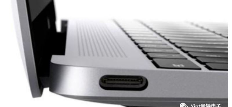
Socket signal transmission USB 3.1 (TX and RX pair) and USB 2.0 (D+ and D−) data bus, USB power (VBUS), ground (GND), configuration channel signals (CC1 and CC2), and two sidebands (SBU) ) Signal pin. The two sets of USB data bus signal positions in this layout support USB signal mapping. This operation is completely independent of the direction of the plug in the socket.
USB Type-C plug interface (front view)
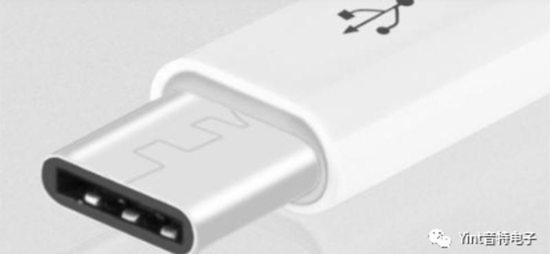
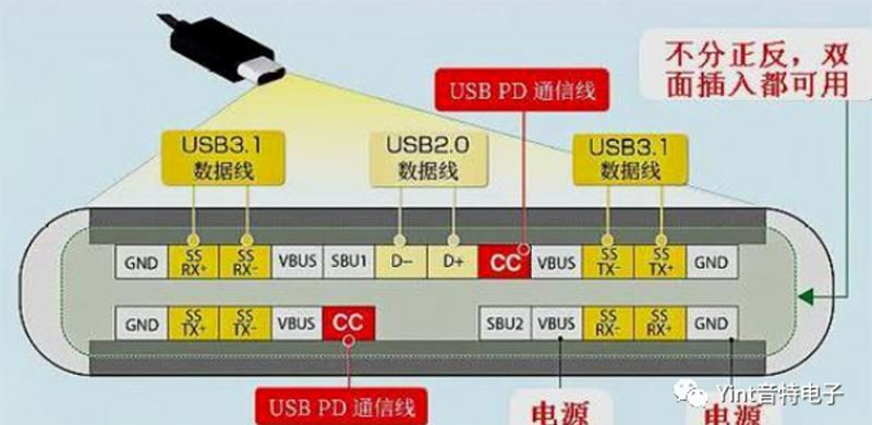
USB Type-C plug signal. Only one CC pin is connected through the cable to determine the signal direction; the other CC pin is used as VCONN to power electronic devices in the USB Type-C plug.

