
 Global


I. Why are Common Mode Inductors Needed?
1.1 Interference on the CAN bus primarily originates from common-mode noise and differential-mode noise. Common-mode noise, often caused by ground loops and EMI (Electromagnetic Interference), is simultaneously induced in both signal lines, with its voltage potential referenced to ground.
For example: In complex electromagnetic environments, EMI generated by the operation of nearby large electrical equipment may couple into the CAN bus via space, forming common-mode noise. Differential-mode noise is primarily caused by signal crosstalk, arising between the two transmission lines. For instance, during high-speed data transmission, signals on adjacent lines may interfere with each other, leading to differential-mode noise.
2.1 The main function of a common mode inductor is to suppress common-mode noise without affecting the transmission of differential-mode signals.
When common-mode current flows through the common mode inductor, the magnetic flux lines formed in the magnetic core superimpose due to its special winding configuration, presenting a high impedance to the common-mode current, thus effectively attenuating common-mode noise. For differential-mode signals, the magnetic flux lines cancel each other out, and only coil resistance and minimal leakage inductance affect them, allowing them to pass through almost without attenuation.
Furthermore, common mode inductors help meet EMC standards such as CISPR 25/EN 61000, etc. In the automotive electronics field, CISPR 25 standards impose strict limits on conducted emissions. Many CAN transceivers exceed these limits without a common mode inductor. Adding a 51µH common mode inductor shows significant noise improvement across various frequency bands, enabling the system to pass tests.
3.1 Placement of Common Mode Inductors in CAN Networks
Common mode inductors in CAN networks are typically placed close to the transceiver and are often paralleled with a 120Ω termination resistor. Placement near the transceiver more effectively suppresses common-mode noise at the transceiver interface, reducing its impact on signal transmission. Paralleling the 120Ω termination resistor matches the characteristic impedance of the CAN bus (typically 120Ω), preventing signal reflection and ensuring signal quality. Impedance mismatch can cause signal reflection at the receiving end, leading to signal ringing on the bus and affecting normal CAN communication.
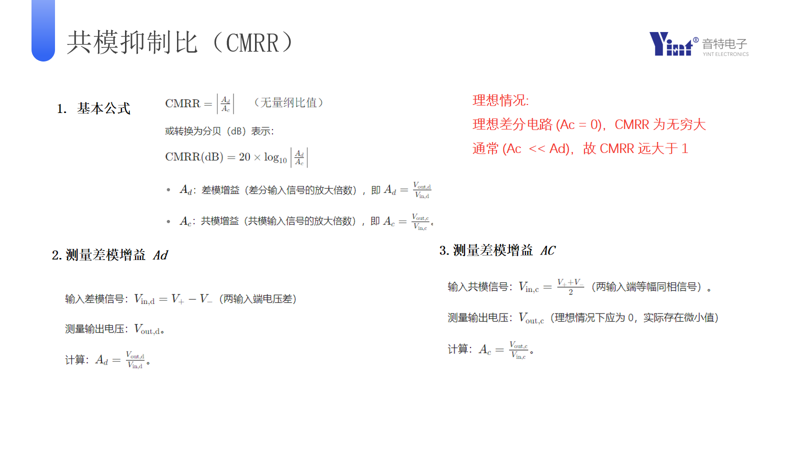
Common Mode Rejection Ratio (CMRR) is a key indicator of a common mode inductor's ability to suppress common-mode signals. A higher CMRR indicates better suppression of common-mode noise, more effective attenuation of common-mode interference, and enhanced CAN bus immunity. Parasitic capacitance affects the high-frequency performance of common mode inductors. At high frequencies, parasitic capacitance presents low impedance, potentially allowing some high-frequency signals to leak through, thereby reducing the inductor's effectiveness in suppressing high-frequency common-mode noise. Therefore, in high-frequency applications, special attention must be paid to the parasitic capacitance parameter of the common mode inductor.
II. 51µH vs. 100µH: Core Differences
2.1 Inductance Value Difference
51µH represents a low inductance value, offering good high-frequency response. It effectively suppresses common-mode noise at higher frequencies, making it suitable for high-frequency signal transmission scenarios.
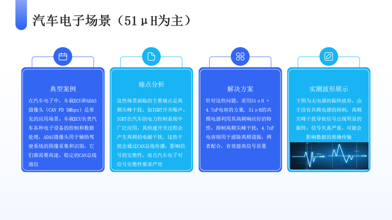
For example: In automotive electronics for CAN FD 5 Mbps high-speed communication, a 51µH common mode inductor can effectively handle high-frequency spike interference.
100µH represents a high inductance value, providing strong low-frequency suppression. It has a better attenuation effect on low-frequency common-mode noise, making it more suitable for environments with more low-frequency interference.
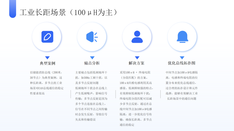
For example: For 50 Hz power frequency interference present in industrial long-distance energy storage fire protection buses, a 100µH common mode inductor can leverage its low-frequency suppression advantage.
2.2 Parasitic Capacitance Comparison
A 51µH inductor typically has a parasitic capacitance < 10 pF. This low parasitic capacitance makes it suitable for high-speed signal transmission, as it minimizes signal leakage and distortion, ensuring signal integrity.
A 100µH inductor typically has a parasitic capacitance between 15 - 20 pF. The relatively higher parasitic capacitance may cause resonance issues at high frequencies, affecting signal quality. Therefore, special attention to resonance phenomena is needed when using a 100µH common mode inductor, and appropriate measures should be taken if necessary to avoid signal interference.
2.3 DC Resistance (DCR) Difference
A 51µH inductor typically has a DC resistance < 50 mΩ. Lower DC resistance means less power dissipation in the circuit, which helps reduce system energy consumption and improves energy efficiency.
A 100µH inductor typically has a DC resistance between 80 - 120 mΩ. The relatively higher DC resistance requires consideration of its impact on signal loss during long-distance transmission. The resistance causes signal attenuation, potentially affecting signal quality and transmission distance.
2.4 Size and Cost
Both 51µH and 100µH inductors often use small-sized packages such as 4532/1812in, 3225/1206. Smaller sizes occupy less space on the PCB, facilitating design and integration. Cost is relatively lower, offering an advantage in cost-sensitive projects. However, as the size decreases, the demands on process and materials increase, potentially raising costs! The relationship between size and cost often resembles a "U-shaped curve" or "smile curve."
III. Design Pitfalls and Test Verification
3.1 Use 100µH with Caution in High-Speed Buses
In buses operating at 5 Mbps or higher, use 100µH common mode inductors with caution. Due to their relatively larger parasitic capacitance, 100µH inductors may cause significant overshoot on the signal rising edge during high-speed transmission, affecting signal quality and communication stability. Typically, overshoot should be ≤ 20%. If using a 100µH inductor causes overshoot to exceed this standard, reconsider the selection or take other optimization measures.
3.2 Long-Distance Buses Require Compensation
When using a 100µH common mode inductor in a long-distance bus, pair it with a 4.7 nF capacitor for compensation to avoid LC resonance. The 100µH inductor and distributed bus capacitance may form an LC resonant circuit, causing severe signal distortion at specific frequencies. Adding a 4.7 nF capacitor can modify the circuit's impedance characteristics, preventing resonance and ensuring signal stability over long distances.
3.3 Hot-Swap Scenarios
In hot-swap scenarios, prioritize selecting a 51µH common mode inductor. The lower inductance of 51µH results in smaller transient voltages during hot-swap events, reducing the risk of damage to transceivers and other equipment. A 100µH inductor, with its higher inductance, generates larger transient voltages during hot-swaps, which could potentially damage equipment. Therefore, 51µH is a more suitable choice for frequent hot-swap scenarios.
IV. Test Verification Process
4.1 Oscilloscope Measurement
Use an oscilloscope to measure the eye diagram of the differential signal. Requirements: For a 51µH inductor, eye width should be > 80%; for a 100µH inductor, eye width should be > 70%. The eye diagram is a crucial tool for assessing digital signal transmission quality. A wider eye width indicates greater noise margin and more reliable signal transmission. Observing the eye diagram provides an intuitive understanding of signal quality and stability.
4.2 EMC Testing
Perform conducted emission testing. For the CISPR 25 Class 2 standard, conducted emissions must be ≤ -45 dBµV. Conducted emission testing detects electromagnetic interference emitted by the device via power or signal lines, ensuring compliance with relevant EMC standards and preventing interference with other equipment.
4.3 Environmental Simulation
Test within a motor interference chamber. Requirements for a 100µH common mode inductor: attenuation > 20 dB within the 100 kHz - 10 MHz frequency range. Motors generate complex electromagnetic interference during operation. Testing in a motor interference chamber simulates this environment, allowing evaluation of the common mode inductor's performance under realistic interference conditions and its suppression capability across different frequencies.
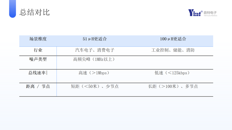
V. Summary Comparison Table
Appendix (Optional)
51µH Common Mode Inductor References: TDK ACT45B-510, Murata LQW18AN510M, Yinte Electronic Models: CML4532A-510T, CML3225A-510T.
These 51µH inductors offer good high-frequency response, low parasitic capacitance, and low DC resistance, making them suitable for automotive electronics and high-speed data transmission.
100µH Common Mode Inductor References: Coilcraft XEL1040-101M, Yinte Electronic Models: CML4532A-101T, CML3225A-101T.
These 100µH inductors effectively suppress low-frequency interference and, with their larger package sizes, meet the performance requirements for long-distance, multi-node communication.
CAN Protocol Standards
Core Standard: ISO 11898-1:2024 (latest version) - Data link layer and physical layer.
ISO 11898-2:2016 - Specifies electrical characteristics for high-speed CAN (e.g., differential voltage, 120Ω termination resistor), applicable to high-bandwidth scenarios like automotive powertrain systems.
ISO 11898-4:2004 - Time-Triggered CAN (TTCAN), used for industrial control requiring precise synchronization.
ISO 11898-5:2007 - Low-power CAN, suitable for energy-saving scenarios (e.g., vehicle sleep modes).
ISO 11519-2:1994 - Former standard for low-speed CAN (<125 kbit/s) physical layer, now superseded by ISO 11898-3, but still used in some legacy systems.
ISO 15765 (ISO-TP) - Defines transport protocol on CAN bus, addressing the 8-byte payload limit and supporting long message segmentation.
ISO 14229 (UDS) - Unified Diagnostic Services, implemented over CAN for remote vehicle ECU diagnostics (e.g., reading fault codes, programming).
Automotive Field: J1939 (commercial vehicles), ISO 11783 (agricultural machinery).
Industrial Field: CANopen, DeviceNet, and other higher-layer protocols are based on ISO 11898.
 Hot News


 沪公网安备31011702889749号

