
 Global


01 Inductor Basics and Importance
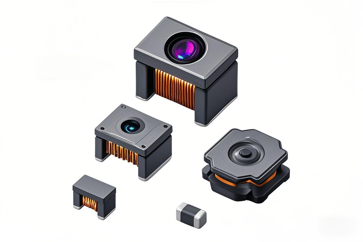
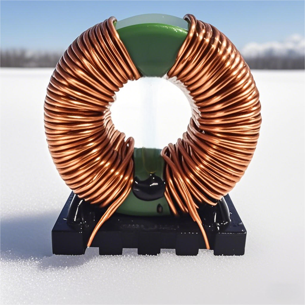
An inductor is a component that can convert electrical energy into magnetic energy and store it. Its structure is similar to a transformer but with only one winding. It possesses a certain inductance, characterized by allowing DC to pass while impeding AC. When current flows through a conductor, it generates an electromagnetic field. Inductance is the physical quantity that measures a coil's ability to produce electromagnetic induction. Passing current through a coil generates a magnetic field around it, resulting in magnetic flux. The greater the current, the stronger the magnetic field and the larger the magnetic flux. The ratio of the magnetic flux through the coil to the current passed is called the self-inductance coefficient, which is the inductance.
1.1 Functions of Inductors
Pass DC, Block AC: Isolate or filter AC signals, or form resonant circuits with capacitors and resistors. They limit AC current and can form high-pass or low-pass filters, phase-shift circuits, and resonant circuits with resistors or capacitors. Tuning and Frequency Selection: An inductor coil and a capacitor in parallel can form an LC tuning circuit. When the circuit's natural oscillation frequency equals the frequency of an external AC signal, the inductive and capacitive reactances are equal, causing electromagnetic energy to oscillate back and forth between the inductor and capacitor—this is LC circuit resonance. At resonance, the total circuit reactance is minimal, and the current is maximum, giving the LC resonant circuit frequency-selective properties, allowing it to select a specific frequency AC signal.
Signal Selection, Noise Filtering, Current Stabilization, and EMI Suppression: For example, ferrite beads and connecting cables form an inductor, a common anti-interference component in electronic circuits that provides good shielding against high-frequency noise. Useful signals pass through smoothly, while high-frequency interference is effectively suppressed.
1.2 Applications of Inductors in Circuits
02 Preparations Before Selection
Clarify Circuit Requirements
2.1 Determining the circuit's operating frequency range is crucial because inductor performance varies at different frequencies. For example, inductors for high-frequency signals typically operate at high frequencies, generally above 1 GHz, with resonant frequencies as high as 12 GHz. General-purpose signal inductors have relatively lower operating frequencies, with resonant points typically within a few hundred megahertz.
2.2 Understand the circuit's requirements for signal integrity. For circuits demanding high signal accuracy and stability, choose inductors that ensure high-quality signal transmission, avoiding signal distortion and interference.
Consider Environmental Factors
2.3 Ambient temperature significantly impacts inductor performance. Temperature changes can alter inductor parameters. For instance, high temperatures may increase material resistivity, reducing Q-factor and increasing inductor losses. Therefore, clearly define the operating temperature range and select inductors with stable performance within that range.
2.4 Humidity can also affect inductor performance, especially for inductors without adequate protection. Moist environments may cause internal components to rust or corrode, affecting normal operation.
Understand Cost Constraints
While meeting circuit performance requirements, cost is a key consideration. Prices vary significantly among different types, specifications, and brands of inductors, requiring a balance between performance and cost. For example, some high-end inductors offer superior performance but are expensive. If circuit performance requirements are not extremely demanding, more cost-effective inductors can be chosen. Also, consider long-term usage costs, including stability, reliability, and potential maintenance costs.
03 Core Selection Principles
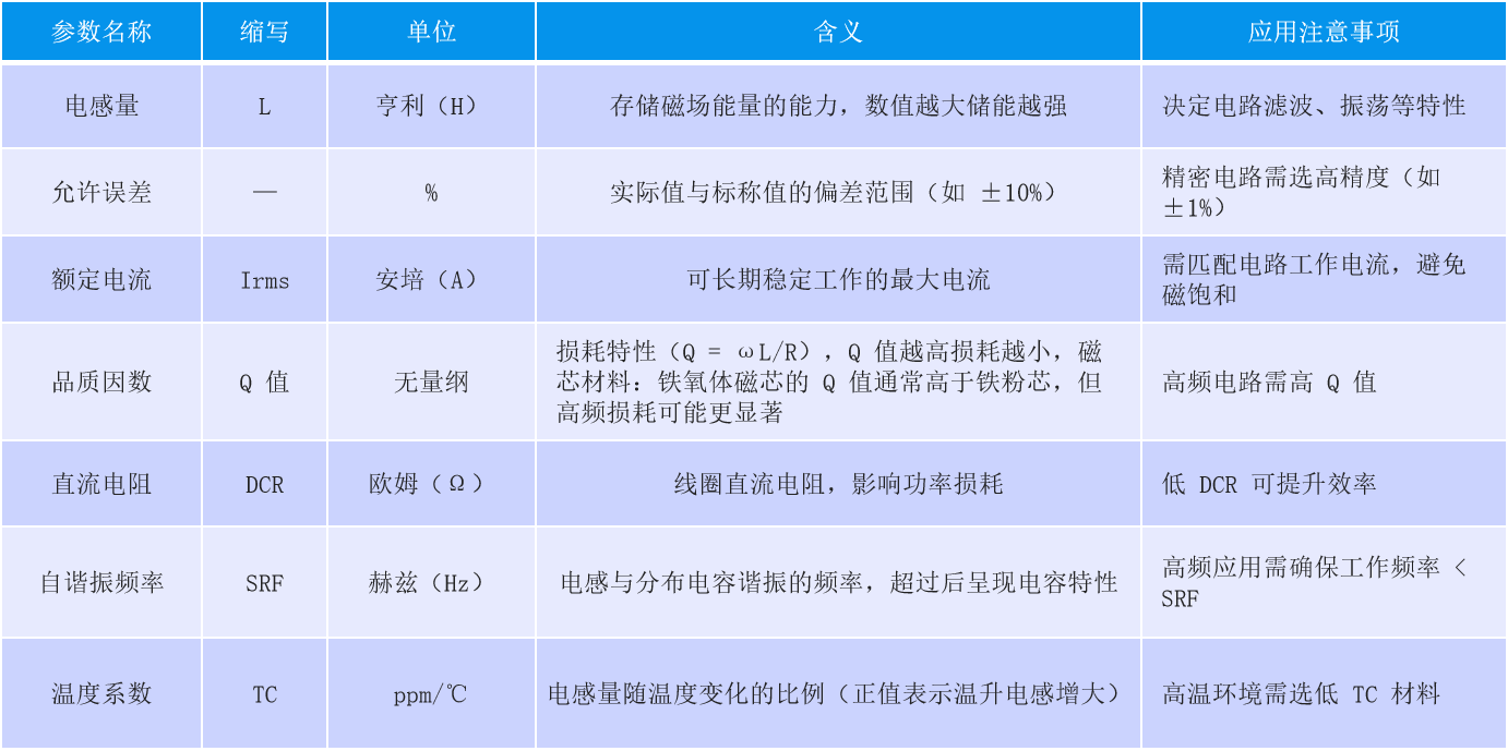
3.1 Inductance Value Selection
Determine the appropriate inductance value based on the circuit's specific function and design requirements. For example, in LC oscillator circuits, the inductance and capacitance jointly determine the oscillation frequency. In filter circuits, inductance affects filtering effectiveness and frequency characteristics.
Pay attention to the inductance tolerance range. General inductance tolerances are ±10% to ±20%. For circuits requiring high inductance accuracy, choose inductors with smaller tolerances to avoid performance instability due to inductance deviation.
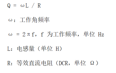
3.2 Quality Factor (Q-factor)
Q-factor, also called the quality factor, is the ratio of an inductor's ability to store energy to its energy dissipation as heat. It reflects inductor efficiency in AC circuits. Generally, higher Q-factor indicates better performance. Q-factor is influenced by material, frequency, temperature, and manufacturing process. High-permeability materials can reduce losses, increasing Q-factor. Q-factor typically decreases with increasing frequency. Rising temperature increases material resistivity, potentially lowering Q-factor. Manufacturing processes, including coil winding and core assembly, also affect Q-factor. In high-frequency circuits, high-Q inductors help reduce signal distortion, improve signal integrity, lower losses, and enhance circuit efficiency and stability.
3.3 Importance of DC Resistance (DCR)
DC resistance is the DC internal resistance of the inductor winding. Its magnitude affects DC power loss and temperature rise in the circuit. Higher DCR results in greater power dissipation across the inductor at the same current, causing heating and impacting circuit stability and efficiency. When selecting inductors, prioritize low DCR while meeting other performance requirements to reduce energy loss and heating issues. For example, in high-current power supply circuits, low-DCR inductors can effectively reduce voltage drop and improve power supply efficiency.
3.4 Self-Resonant Frequency (SRF)
Due to the presence of parasitic capacitance, LC oscillation occurs, and its resonant frequency is the inductor's self-resonant frequency. Before the SRF, the inductor's impedance increases with frequency; after the SRF, the impedance decreases with frequency, exhibiting capacitive behavior.
In practical applications, select inductors whose SRF is higher than the operating frequency to ensure the inductor behaves inductively within the operating frequency range and functions as intended. If the operating frequency exceeds the SRF, the inductor loses its inductive characteristics and fails to work properly.
3.5 Determining Rated Current
Rated current includes inductor saturation current (Isat) and inductor temperature rise current (Irms). Generally, the smaller of Isat and Irms is taken as the inductor's rated current. Inductor saturation current (Isat) is the DC current at which the inductance value drops by 30%. Inductor temperature rise current (Irms) is the DC current that causes the inductor temperature to rise by 40℃ from a 20℃ ambient.
The inductor's operating current must be less than the rated current; otherwise, the inductance value will change, affecting normal circuit operation. During circuit design, based on the maximum circuit current, select inductors with a sufficiently high rated current, leaving a margin. It is generally recommended that the rated current be 1.3 times the maximum output current, derating for use to improve circuit reliability.
04 Selection Misconceptions and Precautions
Focusing solely on one inductor parameter while ignoring others. For example, pursuing high Q-factor without considering whether the inductance value, rated current, etc., meet circuit requirements may prevent proper circuit operation. Ignoring the inductor's operating environment, such as temperature and humidity, and selecting inductors with unstable performance in actual conditions can affect circuit reliability and stability.
Precautions
4.1 When selecting inductors, comprehensively consider multiple parameters to ensure each meets circuit requirements and works harmoniously for optimal circuit performance.
4.2 Refer to the inductor's datasheet to understand detailed parameters, performance curves, and application notes, aiding in correct selection and usage.
4.3 For special application scenarios like high temperature, high voltage, or high frequency, choose inductors specifically designed for such environments to ensure reliability and stability.
05 Summary
5.1 Core principles for inductor selection include determining the appropriate inductance value based on circuit requirements, focusing on the quality factor (Q) to improve efficiency and signal quality, selecting inductors with low DC resistance (DCR) to reduce energy loss and heating, ensuring the self-resonant frequency (SRF) is above the operating frequency to maintain inductive characteristics, and determining a suitable rated current with sufficient margin and derating for use.
5.2 Correct inductor selection is crucial for circuit performance, stability, and reliability. Suitable inductors ensure normal circuit operation, improve signal quality, reduce energy loss, lower the probability of failures, thereby enhancing the performance and lifespan of the entire electronic device.
With the continuous development of electronic technology, demands on inductor performance are increasing. Future inductors may evolve towards smaller size, higher performance, and lower loss to meet the needs of increasingly miniaturized and high-performance electronic devices. Simultaneously, the application of new materials and manufacturing processes will bring new opportunities and breakthroughs in inductor development.
 Hot News


 沪公网安备31011702889749号

