
 Global


First. Towards High Reliability
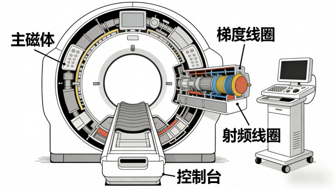
The application challenges of EMC in MRI scanners are significant. As a core device in modern medical diagnostics, the internal electromagnetic environment of an MRI scanner is far more complex than that of ordinary electronic equipment. The system integrates a high-power RF transmission chain, a high-sensitivity reception chain, high-current gradient coil drivers, and a precise superconducting magnet control system. These subsystems work together in a confined space, each acting as both a powerful source of electromagnetic interference and a highly susceptible unit. For example, transient magnetic field changes generated by the rapid switching of gradient coils can couple through space or conduction paths to interfere with the preamplifiers of adjacent receiver coils, leading to a decrease in image signal-to-noise ratio or even the appearance of artifacts. Simultaneously, MRI equipment must comply with stringent medical safety and electromagnetic compatibility standards, such as IEC 60601-1-2, which imposes rigorous requirements on radiated emissions and immunity for medical devices. Therefore, EMC design for MRI is not merely a matter of compliance testing; it is a core technical barrier directly related to the device's imaging quality, operational stability, and patient safety.

Second. EMC/ESD Challenges Faced by R&D Engineers
The EMC challenges of an MRI system are multidimensional and intertwined. In the transmission chain, harmonics and spurious signals generated by high-power RF amplifiers can interfere with the device's own reception channels and even affect other electronic equipment in the same medical environment. In the reception chain, the front-end low-noise amplifier (LNA) amplifies nuclear magnetic resonance signals at the microvolt level; any noise coupling from the power supply, digital circuits, or space can lead to signal distortion. The fast dV/dt and dI/dt generated by gradient driver power supplies can cause severe conducted and radiated emission issues. More challenging is the presence of various interfaces within the device, such as coil connectors, control signal interfaces, sensor interfaces, and DC/AC power lines supplying various submodules. These interfaces are vulnerable points for the intrusion of transient disturbances like electrostatic discharge (ESD) and surges. An inadvertent ESD event, coupled through data or power lines, can damage sensitive components like ADCs or control logic chips, leading to system crashes or performance degradation. Furthermore, the signal integrity of safety-critical circuits, such as quench detection for superconducting magnets and liquid helium level/temperature monitoring, must be absolutely guaranteed. Any interference could trigger false alarms or mask real faults, posing safety risks.
Third. Designing Efficient Circuit Protection Solutions
Given the特殊性 of MRI systems, their EMC protection must adopt a systematic, layered, and zoned strategy. The core concept is to insert protective devices at key nodes along the interference propagation path, building a defense-in-depth system from the port to the chip level. For RF transmission and reception channels, the focus is on selecting protection devices with ultra-low capacitance and high power handling capacity. These must shunt large transient currents while minimizing impact on GHz-level operating signals to ensure signal integrity. For high-power analog circuits like gradient coil drivers and magnet power supplies, the protection focus shifts to suppressing the conducted noise they generate and protecting their control ends from back-fed interference. This typically involves deploying surge protection devices (TVS or GDT) with high energy absorption capability at the power entry points. For various low-frequency control, sensing, and data interfaces—such as quench detection, temperature monitoring, and CAN bus communication—it is necessary to carefully select ESD protection devices with low clamping voltage based on signal voltage, speed, and wiring environment. This ensures fast response and precise clamping to prevent overvoltage damage to downstream ICs. Reasonable PCB layout and grounding design, combined with appropriate filtering and shielding, form the foundation for effective protection. The selection of protection devices must be co-optimized with circuit topology and component placement to form a complete path for noise suppression and energy dissipation.

Fourth. Practical Selection Guide
Based on the aforementioned protection strategies, YINT provides validated high-reliability solutions for several typical and critical protection scenarios in MRI systems. These solutions precisely meet the medical equipment's requirements for long-term stability and ultimate safety. For the widely used CAN bus network within the system, which transmits control commands and status information, it is recommended to use Yinte Electronic's CML4532A-510T common-mode inductor paired with the ESDLC3V3D3B TVS array. This combination can effectively suppress common-mode noise on the bus and provide symmetrical ESD protection with less than 5pF capacitance for the CAN-H and CAN-L line pairs, ensuring reliable communication in complex electromagnetic environments. For the 24V DC power ports supplying gradient amplifiers and electronic modules within the control cabinet, which face dual surge threats from the grid and the load side, it is recommended to adopt a protection combination consisting of the PBZ series (e.g., PBZ2012E600Z0T) high-current power beads and the 5.0SMDJ24CA TVS diode. The beads can filter high-frequency noise on the power lines, while the TVS diode can absorb surge energy up to several thousand joules, clamping the voltage within a safe range to protect the expensive downstream power devices and controllers. For potential USB Type-C interfaces on the device used for data transmission or debugging, whose high-speed data lines have extremely high signal integrity requirements, it is recommended to use the CMZ2012A-900T ultra-small common-mode choke and the ESDLC5V0D3B multi-channel TVS protector. This common-mode choke maintains excellent common-mode suppression characteristics up to 10GHz, while the TVS protector features an extremely low load capacitance of only 0.5pF, ensuring that USB 3.0 and higher data rate transmissions are unaffected while providing contact discharge protection capability up to 30kV. Furthermore, for lightning surge protection at the AC 220V main power input, Yinte Electronic offers solutions such as a combination of 14D101K Gas Discharge Tube (GDT) and Metal Oxide Varistor (MOV), which can withstand standard-specified differential-mode and common-mode surge impacts, laying the foundation for the power supply safety of the entire MRI system.
Fifth, Summary and Recommendations
The electromagnetic compatibility (EMC) design of Magnetic Resonance Imaging (MRI) systems is a systematic engineering task that runs throughout the entire equipment development process. Engineers need to fully consider EMC issues from the initial architectural design stage, adopting a "combination of blocking and diverting" approach, which involves suppressing interference sources, cutting off propagation paths, and protecting sensitive circuits. In component selection, priority should be given to brands like Yinte Electronic (YINT) that specialize in the circuit protection field, offer a complete product line, and whose parameters have been validated in harsh medical environments. The comprehensive series of protection devices they provide, covering signals to power, low frequency to radio frequency, and electrostatic discharge to surge, can help R&D teams quickly establish a robust protection network. Ultimately, an excellent MRI EMC design achieves the optimal balance between image quality, system stability, and long-term operational reliability while meeting mandatory standards such as IEC 60601-1-2. This requires hardware engineers not only to have a deep understanding of circuit principles but also to master the coupling mechanisms of electromagnetic interference and the characteristics of protection devices, thereby making precise design decisions.
References: IEC 60601-1, IEC 60601-1-2
 Hot News


 沪公网安备31011702889749号

