
 Global


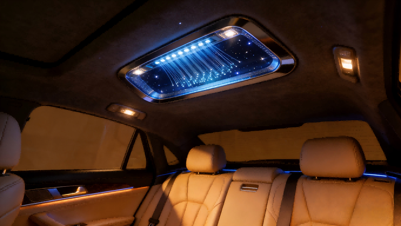
In luxury automotive cockpits, starry sky headliner modules are evolving from high-end optional features to key configurations that express personalization. Composed of hundreds or even thousands of micro-LEDs or optical fibers, this sophisticated lighting system presents core challenges that go far beyond creating a stunning visual spectacle.
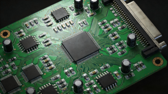
As engineers shift their focus from aesthetic design to circuit boards, a harsh reality emerges: this precision optoelectronic system operates in what can be described as an extremely harsh electromagnetic "battlefield."
The typical power consumption of a starry sky headliner module ranges from 16W to 48W. This translates to an operating current of 1.3A to 4A in a 12V system. However, according to the ISO 16750-2 standard, automotive electrical systems must withstand a series of rigorous tests. For instance, a load dump can generate high-voltage pulses reaching tens of volts and lasting hundreds of milliseconds. During a cold crank, the voltage can plummet below 6V. Ordinary linear regulators or simple switching power supply solutions are powerless against such violent transient events.
A more insidious threat comes from conducted electromagnetic interference. The control unit of the starry sky headliner typically uses PWM signals (frequency ≥ 400Hz) for dimming and color control, making it a potential source of interference itself. Simultaneously, it is highly susceptible to switching noise from other loads on the same power network, such as window motors, fuel pumps, and ignition coils. These high-frequency noises can couple into sensitive analog dimming circuits or communication lines, causing visible LED flicker, color temperature drift, or even control logic disruption. Traditional solutions might only employ a simple fuse and Zener diode, which are completely inadequate for handling complex EMS threats.
To protect this "starry sky," it is essential to establish a comprehensive, multi-layered protection system from the power entry point to every signal terminal. This requires a solution that possesses both excellent electromagnetic interference suppression capability and robust electromagnetic immunity.
The First Line of Defense: Surge and Noise Suppression at the Power Input
The power input port is where energy is greatest and threats are most direct. For a 12V power system, an integrated protection solution must be deployed at the input. First, use a common-mode choke such as the CMZ1211-501T, which effectively filters high-frequency common-mode noise on the power lines, preventing internally generated switching power supply noise from leaking out and blocking external noise intrusion. Immediately following this, robust transient voltage suppressors must be equipped to handle surges. Engineers offer multi-level choices for this scenario: for conventional surge protection, the SM8K24CA or 5.0SMDJ24CA are reliable options. If the system is integrated into a 24V commercial vehicle platform, devices with higher clamping voltages, such as the SM8K33CA, need to be selected. For extremely harsh applications, even Schottky diodes from the SK56/SMC series for reverse polarity protection can be considered, ensuring the safety of downstream circuits even under the most severe load dump conditions.
The starlight headliner module typically needs to communicate with the vehicle body domain controller via CAN or LIN bus to receive commands for switching, dimming modes, etc. These low-speed buses are exposed to the complex electromagnetic environment inside the vehicle and are highly susceptible to electrostatic discharge (ESD) and inductive coupling interference. For LIN bus protection, it is recommended to use the CMLA4532A-510T ferrite bead to suppress high-frequency interference, paired with the ESD1524D3LIN dedicated protection device for ESD protection. For the more common CAN bus, the CML4532A-510T or the smaller CML3225A-101T can be selected as filtering components based on PCB space, while using the ESDLC3V3D3B or ESD24VAPB to provide ESD protection up to ±30kV and surge immunity. This combination of EMI suppression and EMS protection ensures stable and reliable communication, eliminating functional abnormalities caused by signal errors.
Each drive line leading to the LED beads is a potential antenna for receiving and emitting interference. Especially lines routed over long distances to the headliner are more prone to coupling noise. For critical PWM dimming signal lines, ultra-low capacitance TVS arrays can be selected for protection, such as the ESD0524P or ESDSRVLC05-4. These can effectively clamp ESD and EFT pulses, and their extremely low capacitance will not distort the dimming waveform, ensuring uniform color and no flicker.
Assume we are designing a premium starlight headliner system supporting multi-zone color control and communicating via CAN FD. Its power architecture is 12V input, internally containing an MCU, a CAN FD transceiver, and multiple constant-current LED driver chips.
1. Power Input Protection Kit
EMI Filtering: Select the CMZ1211-501T, placed behind the power connector to filter broadband noise.
Surge Suppression: Connect the 5.0SMDJ33CA or 5.0SMDJ36CA in parallel, providing 5000W of peak pulse power to robustly handle load dump.
2. CAN FD Communication Protection Kit
EMI Filtering: Choose the small-sized CML3225A-101T ferrite bead, connected in series on the CAN_H/CAN_L lines to suppress RF interference on the bus.
EMS Protection: Adopt the ESDCANFD24VAPB designed specifically for high-speed buses. This device integrates bidirectional TVS diodes, providing symmetrical protection for the two data lines. Its low clamping voltage and extremely low line-to-line capacitance ensure it does not affect the CAN FD data transmission rate of up to 5 Mbps.
3. Protection for MCU Critical I/O and Dimming Signals
For the PWM signals connected to the driver chip and possible configuration pins (such as I2C), using a multi-channel TVS array is the best choice for saving space; for example, using ESD0524P (4-channel) or ESDSRVLC05-4 (4-channel) can protect multiple signal paths at once, with their extremely low typical capacitance value introducing almost no signal integrity degradation.
Finally: Beyond Protection
EMC Design Enhances System Reliability and Brand Value
Integrating a complete EMI+EMS solution into the starlight headliner module design offers value far beyond merely "passing test certifications"; it directly enhances the reliability of the end product, reduces after-sales failures caused by electromagnetic interference, and protects the luxury reputation of the automotive brand. During PCB layout, ensure that protection devices (such as TVS diodes, ferrite beads) are placed as close as possible to the ports or interference sources to guarantee the shortest discharge path; the loop area between power and ground should be minimized.
For configurations like the starlight headliner that enhance the visual experience, consistent and flawless performance is paramount. A single flicker or color discrepancy can be magnified infinitely within the quiet cabin environment. Therefore, conducting EMC planning from the initial project stages and selecting a complete protection solution that has undergone automotive-grade validation, such as those provided by Yint Electronics, is the optimal path for risk control and quality assurance. It is recommended that engineers clearly specify the model and placement of protection devices for each port during the schematic review stage, laying a solid hardware foundation for the stable and brilliant illumination of this "starry sky within the car."
 Hot News


 沪公网安备31011702889749号

